Our Products
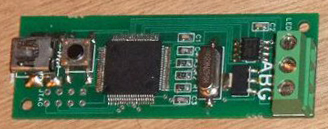
The 16 Zone Local RailCom™ Reader Device
Our RailCom™ Reader device, unlike some others on the market, can cope with more than one RailCom™ enabled locomotive in a single zone, and it can distinguish between Short addresses, Long addresses and Consist addresses, as well as cope with Consist Membership. It can also interleave multiple CV requests simultaneously. Software could use acknowledgements to retire successfully transmitted DCC packets and so reduce unnecessary retransmissions in order to optimise bandwidth usage which may be important on large layouts with many locomotives. It can also differentiate between the 6 different types of acknowledgement codes generated by RailCom™ decoders. Unlike some other available systems, ours will detect simple occupancy by non-RailCom™ enabled decoders, lit coaches or resistive wheel-sets. Furthermore, it will also detect the orientation of RailCom™-equipped locomotives on the tracks and, coupled with the DCC commands, this can then be used to infer direction of travel even before the locomotives have started moving. We are also able to receive values for actual speed, load, fuel, water and temperature and are already capable of implementing any further packet types that may be introduced in the future without requiring any firmware alteration. As an additional measure to guard against data corruption our RailCom™ Reader samples each RailCom bit 5 times, reducing the effect of noise on the RailCom signal significantly.
As the content of RailCom™ packets is still subject to change we decided to avoid depending too heavily on processing the RailCom™ data in hardware and defer as much as possible to the computer. To this end our device supports two methods of transferring RailCom™ data. The first is a raw encoding which transfers everything verbatim. The second provides a degree of preprocessing in hardware and is intended solely for use by the Railroad & Co. / Rocrail compatibility layer.
Our RailCom™ implementation allows a maximum 4096 zones per USB port as opposed to the 1024 from Lenz or 239 from Tams. We believe that ESU and Viessmann will be using an implementation similar to that from Lenz.

Features
- Reads all RailCom signals including RailCom Plus (although no currently available software supports RailCom Plus).
- Firmware easily & safely upgradeable, consequently device is futureproof.
- Reads identity, load, actual speed, temperature, CVs etc. from those decoders which transmit this information.
- Tested with Lenz, Zimo, ESU, Hornby and Tams RailCom decoders.
- Copes with non-spec compliant signals from ESU point controllers.
- Reads locomotive orientation so direction of travel known even when stationary.
- More than one decoder per monitored zone can be read.
- Tams emulation mode available with more in development (e.g. Loconet).
- Dedicated software package in development with enhanced scripting features.
- Can detect simple occupancy as well as RailCom so no separate occupancy detector required.
- Quite simply the most advanced RailCom device made today.
The Omnibus
As most currently available bus systems in use in the Model Railway arena are not fast or powerful enough to manage the data volumes and speeds required by our RailCom™ device, we decided to design a new bus protocol. We intended this bus to be as near universally accessible as possible, hence Omnibus. (Lenz produced their 1Mbit per second RailComBus — probably for these same reasons, but to date have not published their protocol.)
When designing our bus system we first considered, and rejected, various of the other busses already in widespread use. This was primarily because none of the available busses were capable of delivering the 3.6Mbit/s bandwidth required if fully loaded. One bus system which has become fairly popular lately is CANbus, a bus system originally designed for use in the automotive industry. This is the bus system used by Zimo, MERG and the new NMRA standard cab bus. Being one of the few bus systems which are extensible to support RailCom™ we gave it significant consideration before deciding that certain aspects of its design made it unsuitable. Specifically the bus has too much overhead per packet and the fixed priority scheme is in danger of causing starvation of high numbered devices. Consequently we felt we had no choice but to design our own bus system from the ground up.
Our system communicates at variable speeds depending on the devices attached. It will be possible (via adaptors) to attach slower components such as those using s88 or Xpressnet (62.5Kbit/s) alongside fast devices such as our RailCom™ Readers. For now we will run the bus up to 6Mbit/s but the specification is open ended and so may be extended almost indefinitely should it prove desirable (e.g. when fiberoptics become more affordable).
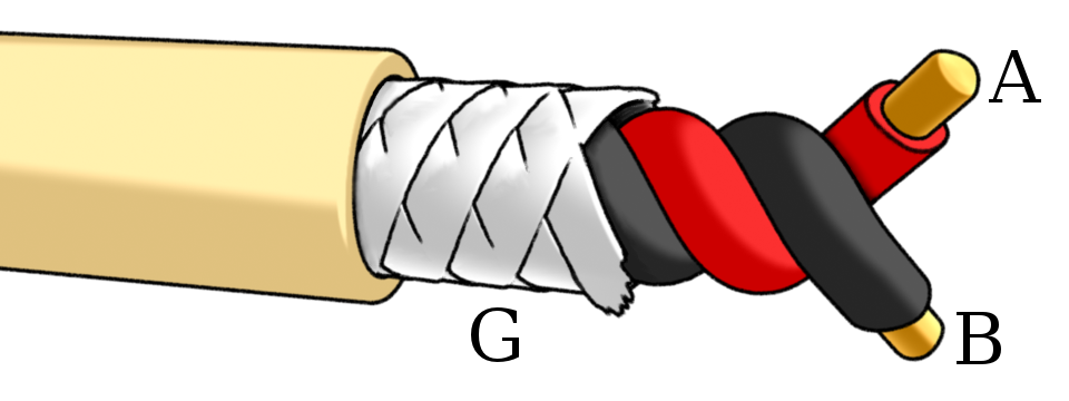
Whereas twisted pair shielded cable (as illustrated below) represents the ideal Omnibus cabling suitable for large layouts, for more modest layouts whatever cable is convenient can be used.
We have made the bus protocol available in the downloads section free of charge so anyone wishing to make compatible devices can.
The Computer Interface Device
Our bus is controlled by our Computer Interface Device (CID) which, somewhat like a traffic policeman on point duty, recognises the various devices connected to the Omnibus at any one time and gives each a turn to deliver their information before packaging this up for the PC. It also receives instructions from the PC which it can communicate to the various occupants and so arbitrate the traffic on the bus.
As part of the Omnibus specification includes a standard method of downloading new firmware to Omnibus devices, the Computer Interface Device supports downloading new firmware both to itself and to all connected Omnibus devices. Additionally the firmware update indicates which devices it is intended to support meaning there is no requirement to disconnect other devices when downloading firmware or to manually download the firmware to one device at a time. Instead if three RailCom™ Reader devices and one DCC Output device are all attached to a Computer Interface Device and a RailCom™ Reader firmware update is performed then all three RailCom™ Reader devices will be updated but both the DCC Output device and the Computer Interface Device will remain untouched. Unlike with certain other manufacturers there is no need for specialised hardware to perform this function.
A potential problem when downloading firmware to a device can occur should the process not complete successfully. This can be caused in many ways e.g. power failure, cables being stepped on causing them to be unplugged, etc. This usually results in the hardware being unusable and requiring repair by the manufacturer. In recognition of this we have designed all our Omnibus equipment to include a button which can restore the firmware to out-of-box condition should a firmware upgrade fail. It works as follows: disconnect power, then hold down the button and reconnect power. After ten seconds the LED will begin to flash red slowly for up to five seconds. If the button is released during this time, then it will flash red quickly before turning green indicating a successful restoration of the firmware to out-of-box condition.
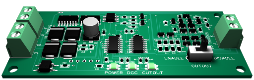
The Standalone Cutout Device
The initial design brief for this circuit was to produce a fully spec compliant DCC cutout so as to allow non-RailCom-enabled hardware to function in a RailCom-enabled environment.
Features
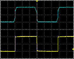
Takes in a DCC signal and corrects any anomalies so as to generate a fully DCC compliant output. Deformities in the DCC signal will be filtered out by this device. Examples include: Asymmetric signals, ringing and distorted square waves. Unfortunately timing errors can't be fixed, however if they are present then this will be indicated by the DCC LED turning red. In the future, our programmable booster will also be able to fix timing errors.
An oscilloscope trace showing the typical repair (shown in yellow) to a DCC signal (shown in blue).
If your system already produces a cutout, but you have equipment such as point accessory decoders or turntable controllers which display anomalous behaviour in the presence of a RailCom cutout, this circuit can be used to selectively remove an existing cutout specifically for those devices.
If your command station or booster is unable to produce a cutout, this circuit can introduce a cutout, enabling you to make use of the features of a RailCom system. This is dependent on the number of preamble bits generated by your command station. The DCC specification mandates a minimum of 14 preamble bits, so if this is all your hardware produces, then only a short cutout can be produced, but with 16 or more preamble bits a long cutout is possible which will enable you to benefit from all the features of RailCom.
This circuit will give you short-circuit protection set to 5A. If the D and E connections are connected to the D and E terminals of your command station, then the cutout device will notify your command station of short-circuit events when they occor.
The cutout device has practically no delay between a change in the incoming signal, and the same change appearing at the output. This makes it possible for a locomotive to move from a cutout-enabled track section to a non-cutout-enabled track section without causing a short-circuit.
For more information see the Cutout Device Manual in the Downloads section.